 Accurate, Productive and Cost-Effective Electromagnetic Signal Integrity Software for Physical Design of Interconnects for Communication Links
Simberian on LinkedIn
Subscribe Simberian channel on LinkedIn...
- #095 Ever wondered why vias are the weakest link in PCB interconnects? Designing vias for PCB and packaging interconnects is a notorious challenge, especially for 112-224Gb signals, as they often cause signal integrity failures due to reflections and crosstalk.
- #094 Is crosstalk the most common cause of PCB/packaging interconnect failures? Not quite — reflections take the top spot.
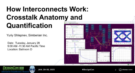
- #093 Exciting New Features in Simbeor 2024.02! We are thrilled to announce the latest updates in Simbeor 2024.02, designed to enhance your signal integrity analysis experience and extend Simbeor's accuracy to mm-wave bandwidth.

- #092 Material Model Identification for PCB and Packaging Interconnects... Simbeor software offers unique feature for dielectric and conductor roughness model identification using GMS-parameters method described in this paper from EPEPS 2015.
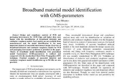
- #091 Unlock the full potential of your AI and ML projects with Simbeor SDK! Simbeor SDK is the industry-first signal integrity analysis automation kit.
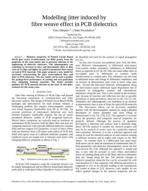
- #090 Fiber-Wave Effect on PCB Interconnects- Mitigate or Evaluate the Impact on Signal? PCB laminates made of woven glass fabric embedded in resin can cause signal integrity issues such as skew, mode conversion, jitter, and even resonances.
- #089 Explore S-parameter Models with Simbeor... S-parameters are the foundation of modern signal integrity. Even when evaluating interconnect compliance in the time domain, S-parameters play a crucial role. But how do you ensure the quality of your simulated or measured S-parameters for accurate analysis?

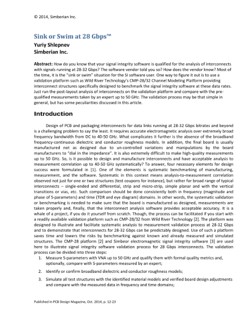
- #088 How do you validate your PCB interconnect analysis or measurements? Are You Sinking or Swimming at 28 Gbps? How confident are you that your PCB interconnect models match real-world measurements? This was the focus of the "Sink or Swim" paper from the October 2014 issue of PCB Design Magazine.
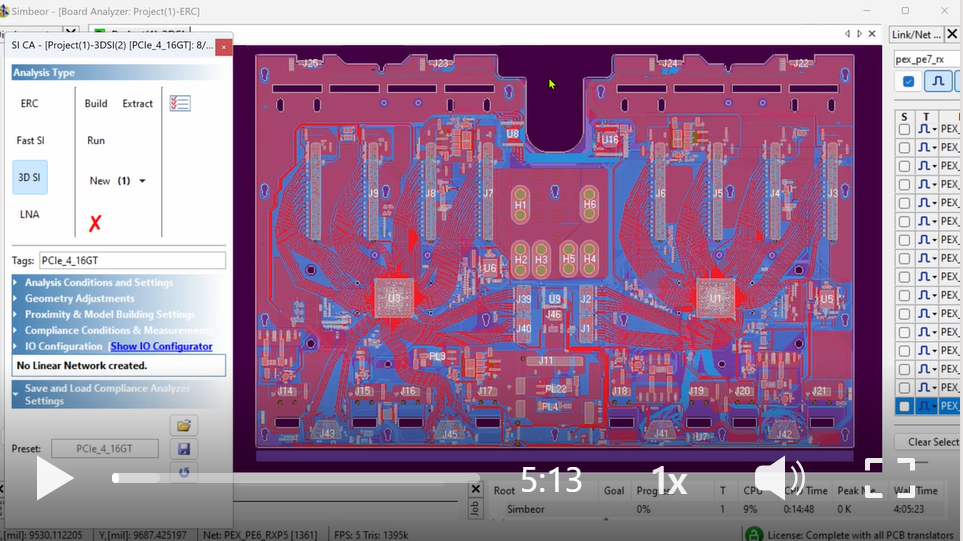
- #087 Simbeor SI Compliance Analyzer: Where Time and Frequency Domains Converge! Watch this demo video to see how Simbeor makes PCB interconnect compliance analysis a breeze. Whether you’re a frequency-domain guru or a time-domain wizard, Simbeor’s got your back!
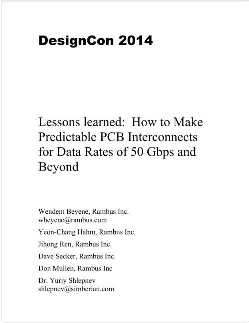
- #086 Decoding 50 Gbps PCB Interconnects: Lessons from the Past! 10 years back, we embarked on a daring mission: design predictable PCB interconnects for data rates beyond 50 Gbps. Buckle up—it’s story time! In this DesignCon 2014 paper we build dielectric and conductor roughness models for low-loss laminates with 50 GHz bandwidth using measured data with the smaller bandwidth and learned some lessons, that are still valuable today.
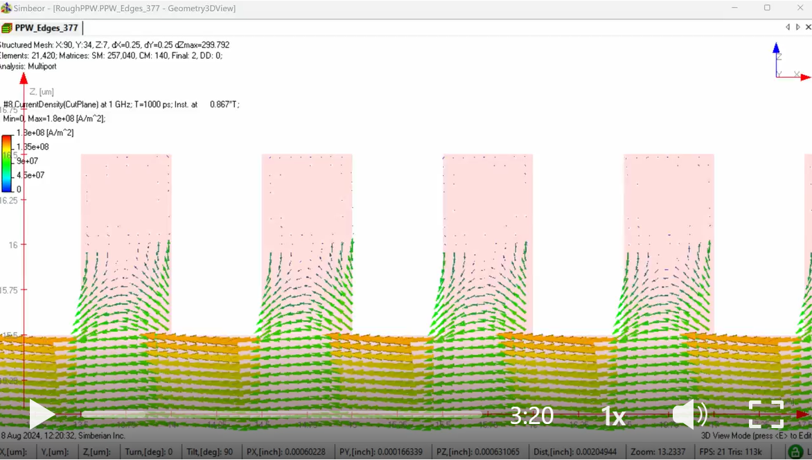
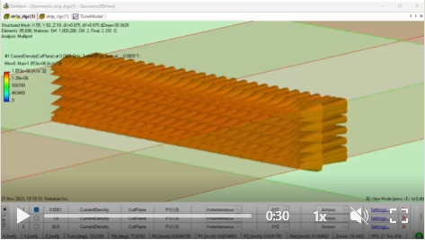
- #085 From 1 GHz to 1 THz, the myth of jumping currents: As we can see, at 1 GHz, currents seem to glide smoothly under the "hurdles". But appearances can be deceiving! The skin depth plays a crucial role.
- #084 The primary goals of PCB interconnect SI analysis are straightforward - to identify interconnects that may fail at the target data rate and to facilitate troubleshooting and resolution of these issues. It should not require a 3DEM analysis of the whole board!

- #083 Is Rz Sufficient for PCB Conductor Roughness Modeling? Short answer: Not really
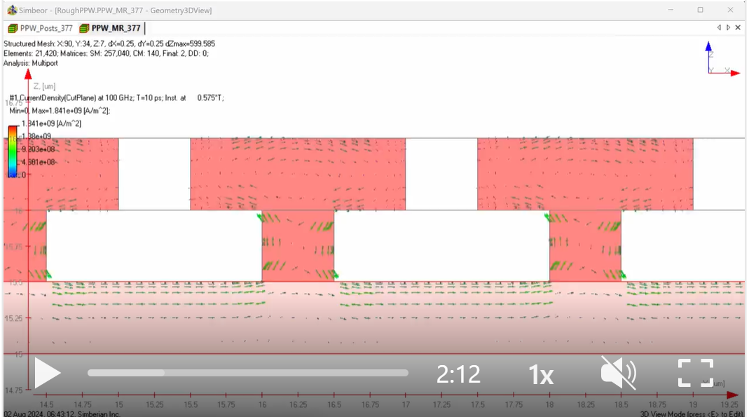
- #082 Currents are weird — they do whatever they want! Try predicting how currents would flow on a surface covered with tiny, mushroom-shaped structures at 100 GHz. Only Maxwell's equations know where they go, but now we do too, thanks to some numerical wizardry.
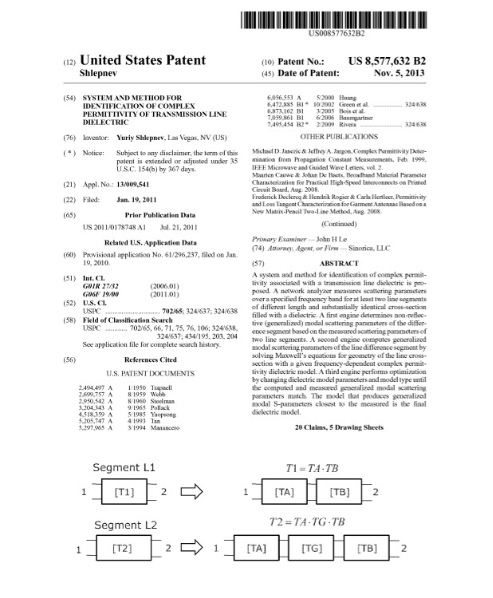
- #081 GMS-parameters or Delta-L: Which Method to Use for Dielectric Model Identification? - a model that can be used in EDA tools to design predictable PCB/Packaging interconnects? The short answer is GMS-parameters technique, described in this 2011/2013 patent and implemented exclusively in Simbeor software.
- #080 Where do currents flow on a rough conductor surface? Do they travel over the bumps or between them?
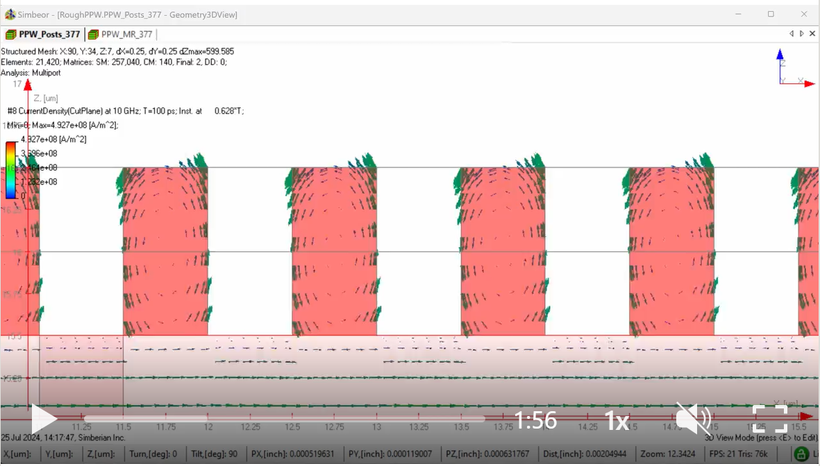
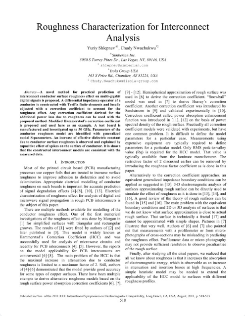
- #079 What conductor roughness model do you use to account for the increase in losses in interconnects? There are many models to choose from - I've counted about 10, and 7 of them are supported in Simbeor software.
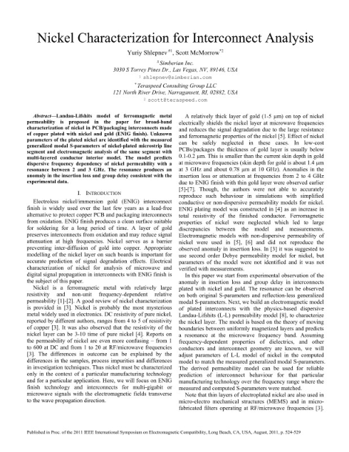
- #078 Considering nickel plating for copper interconnects? Then this paper from EMC 2011 is for you. It demonstrates that the nickel model proposed by Landau and Lifshitz is useful for characterizing interconnects with an ENIG finish.
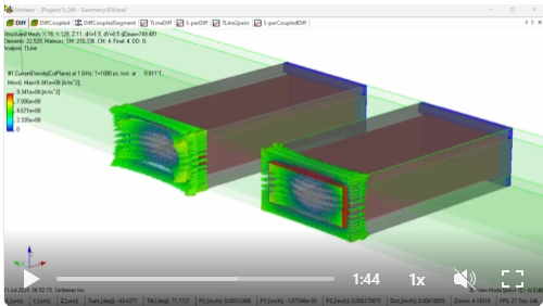
- #077 Understanding Currents with Simbeor Software: Currents in copper interconnects covered with a 0.5um nickel barrier layer are computed and visualized using Simbeor THz software. This video demonstrates one of the unique capabilities of the Simbeor 3DTF Trefftz Finite Element solver.
- #076 Need broadband PCB dielectric and conductor roughness models? The availability of such models is the cornerstone for PCB interconnect predictability. Ever wondered where do they come from? The models with 40-50 GHz bandwidth for 25 Gbps interconnects, as discussed in this DesignCon 2011 paper.
- #075 Think crosstalk modeling and measurement is easy? Think again. Take a look at this seminal paper from DesignCon 2011 that unveils the complexities behind it. A collaboration between industry experts from LeCroy, Simberian, Teraspeed, and Wild River Technology has produced the first-ever systematic approach to the validation of crosstalk on PCB.
- #074 Want to predict PCB/Package interconnect behavior? - then build broadband dielectric and conductor roughness models first...
- #073 This is the presentation from EPEPS2012 on the "Coupled Transmission Planes" or the 2D Telegrapher's equations.

- #072 Does your SI software predicts interconnect behavior? Reflecting on a time when 10 Gbps was the frontier of PCB data rates brings back memories, doesn't it? This DesignCon2009 paper was a trailblazer in the systematic approach to correlating analysis with measurements for designing predictable interconnects.
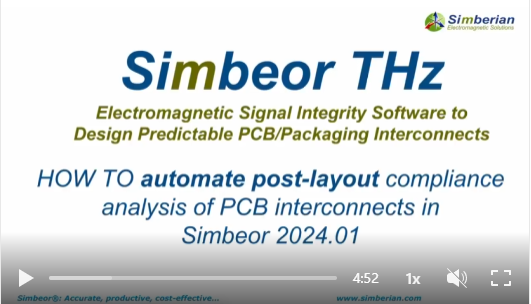
- #071 Wave goodbye to endless clicking and embrace the future of PCB analysis automation with Simbeor 2024.01. Our latest update simplifies the process, as showcased in video.
- #070 Now I know how to say "signal integrity" in French. Démystifier la simulation de l'intégrité du signal d'une carte électronique en pré-routage et en post-routage, jusqu'à 50 Gb/s, avec des nouvelles vidéos de démonstration en français, du simulateur Simbeor v2024.1.
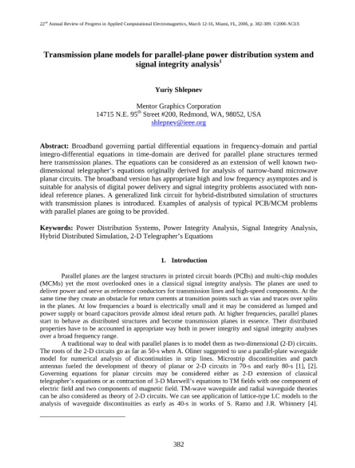
- #069 This paper is on transmission plane models used for analysis of power distribution systems - it is extension of the transmission line concept...
- #068 Have you ever witnessed a LIVE EM SI SOFTWARE DEMO that defies belief? That's what happened when I showcased Simbeor 2024.01 post-layout electromagnetic signal integrity analysis to industry pros during the last few months. Their jaws dropped!

- #067 La nouvelle version de Simbeor v2024.1 vous permet de simuler l'intégrité du signal (impédance, réflexion, diaphonie, diagramme de l'œil, paramètres S...) des signaux multi-cartes d'un système complet...

- #066 This is a LIVE REAL TIME DEMO of a post-layout electromagnetic signal integrity analysis of PCB interconnects...
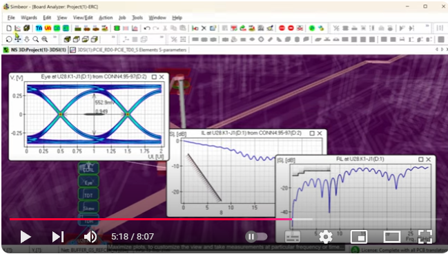
- #065 Are you exploring PCB routing for a specific stackup structure and seeking accurate models for transmission lines and vias? Look no further than Simbeor electromagnetic signal integrity software, your go-to solution. Discover its capabilities in this demo video.

- #064 New visualization and compliance validation capabilities in Simbeor 2024.01 make it extremely easy to do analysis with existing Touchstone models of interconnects.

- #063 We are excited to announce the release of Simbeor 2024.01 with the extensions of the SI Compliance Analyzer for pre-layout, enhanced post-layout and multi-board electromagnetic compliance analyses. The new version extends and facilitates the automatic compliance validation for most of the serial signaling standards, such as IEEE, OIF, PCIe, etc. You can easily run the analysis, check the pass-fail results and view the interactive plots of simulation and compliance results (IL, RL, TDR, PSXT, ICN, ICR, Skew, Delay, etc.).
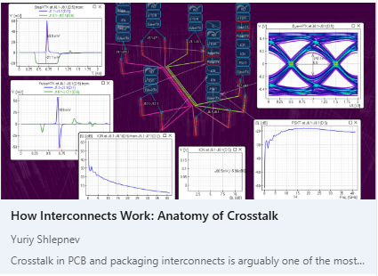
- #062 This is the second part of my paper on the crosstalk in PCB interconnects.
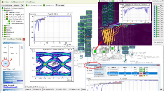
- #061 After four years of intensive development, Simberian is back at DesignCon 2024 with Simbeor, the universal electromagnetic signal integrity software for PCB and packaging interconnects.

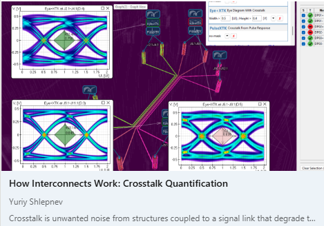
- #060 This is the first part of my article on crosstalk in PCB interconnects.
- #059 How to Ensure Signal Integrity Analysis Accuracy for PCB Interconnects: A 3-Step Guide. Accuracy and validation are crucial for designing and manufacturing PCB interconnects for high-speed interfaces such as PCIe 5. But how can you be sure that your signal integrity software is giving you reliable results?
- #058 What is your favorite "explanation" of the skin-effect in conductors? How do you explain it to yourself? With the Ampere's and Faraday's laws in the integral form? Or with the eddy currents (same thing, but maybe the most popular one)? Or with the Lorentz contraction and Coulomb's low (the most fundamental one)?
- #057 Simbeor 2023 is a universal electromagnetic signal integrity software that can be used not only for compliance verification of serial interconnects, but also for analysis of parallel interconnects.
- #056 I am thrilled to introduce Simbeor 2023.01 (beta), the latest version of our software for signal integrity (SI) analysis of PCB interconnects with automatic compliance verification and interactive plotting.
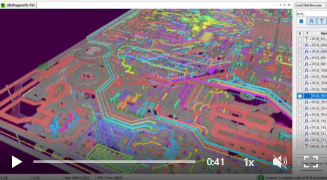
- #055 Here is an overview of PCB/PKG interconnect analysis capabilities of Simbeor software...
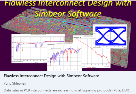
- #054 Have you ever faced a return loss compliance test failure for a PCB link? Like I did in my previous post for 32 GT/s PCIE 5.0 standard. How to fix it?
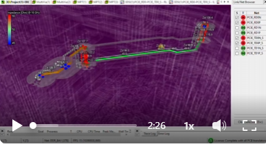
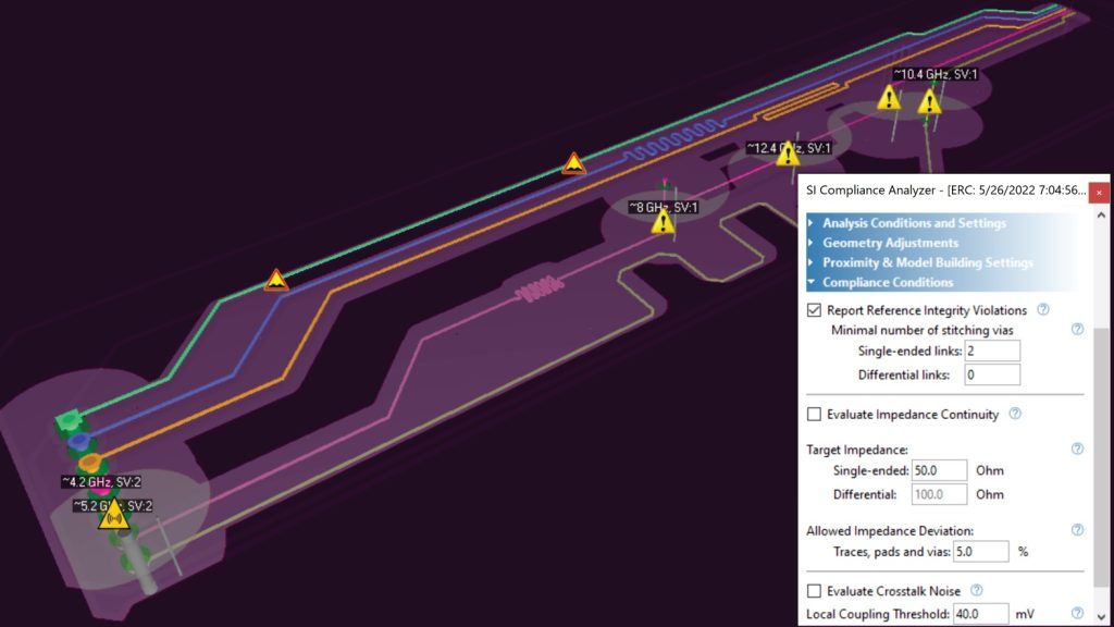
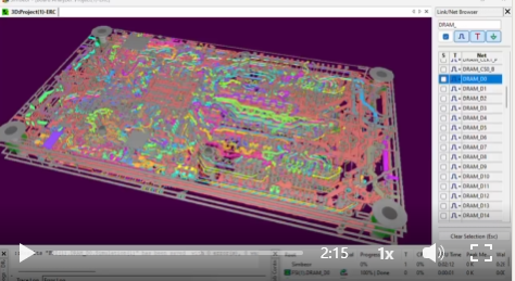
- #053 Planning to migrate PCB design from 16 GT/s PCIe 4.0 to 32 GT/s PCIe 5.0? The analysis of links running at 16 or 32 GT/s (or Gbps) signals must be done with 3D EM analysis and and layout may require optimization. Simulation-based ERC analysis in Simbeor SI Compliance Analyzer is used in this demo for a preliminary evaluation of the link impedance, reference discontinuities and potential aggressors.
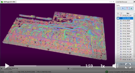
- #052 What can possibly go wrong with a flex PCB design with hatched or meshed planes? You define trace width and spacing using an impedance calculator and simply route them over the hatched planes. Is that it? Maybe. Just to make sure that everything works as intended, load it into Simbeor SI Compliance Analyzer and run simulation-based ERC analysis.
- #051 How to make sure that interconnects designed for a previous generation of DDR will work for the next generation? Just change data rate and run simulation-based ERC analysis in Simbeor SI Compliance Analyzer.
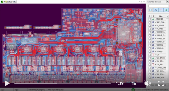
- #050 How do you quantify crosstalk on PCB interconnects? There are multiple ways to do it: local coupling evaluation, pulse or step response crosstalk in time domain, power sum crosstalk (PSXT) and Insertion loss to Crosstalk Ration (ICR) in frequency domain and, finally, Integrated Crosstalk Noise (ICN).
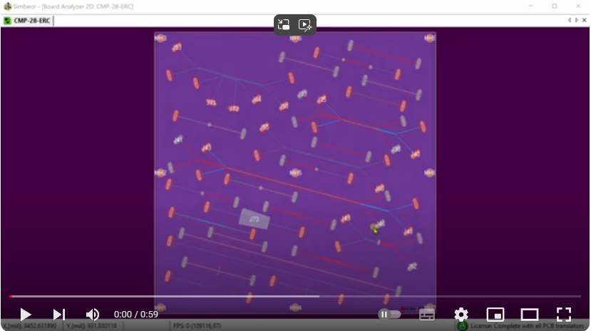
- #049 What is the main reason of crosstalk in PCB and packaging interconnects? If you ask Bing AI, it will give you correct answer about the electric and magnetic coupling. But what is the reason for that coupling?
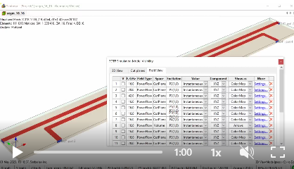
- #048 PCB via-holes can easily destroy the signal, if not properly designed for a particular signaling standard. Well designed via must be localized at least up to the Nyquist frequency and have sufficiently low reflections over a bandwidth of the signal spectrum.
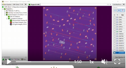
- #047 Does fabric type in PCB laminate increase the delay and impedance uncertainty? The answer is obviously yes, but only...
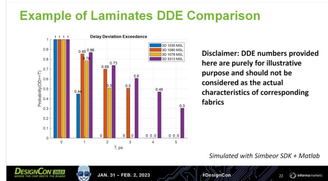
- #046 Want to evaluate possible delay uncertainty due to the fiber weave effect in DDR5/DDR6 links? Now you can do it with the new probabilistic metric introduced last week at DesignCon 2023 in A. Manukovsky, Y. Shlepnev, S. Mordooch, "Impact Evaluation of Fiber-Weave Effect Induced Delay Uncertainty in DDR Data Links on DDR5 & Towards DDR6".
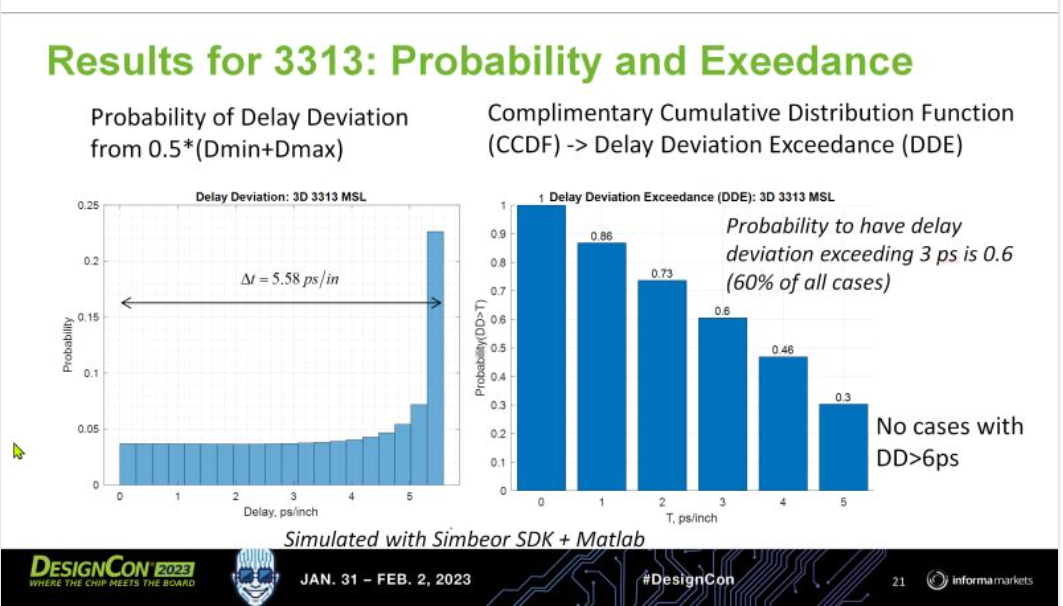
- #045 Should you worry about the Fiber Weave Effect (FWE) on PCB? Yes, but only if you want to use a low-cost laminate, do not apply any FWE mitigation technique due to the cost increase, and have small delay or skew margins.
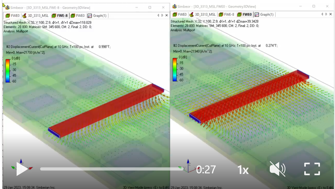
- #044 Is it possible to use the lowest cost PCB laminates for DDR5 and the oncoming DDR6 interconnects and get away with that? Alex Manukovsky asked me question like that about a year ago.
- #043 How to localize differential vias for both differential and common modes? Of course, with more stitching vias!
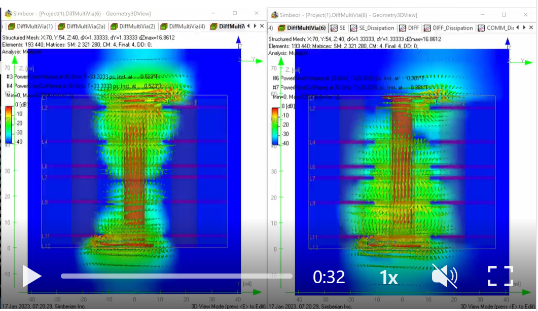
- #042 Two stitching vias at proper locations may be sufficient to localize the differential mode, but what about the common mode? Will it work for the common mode too?
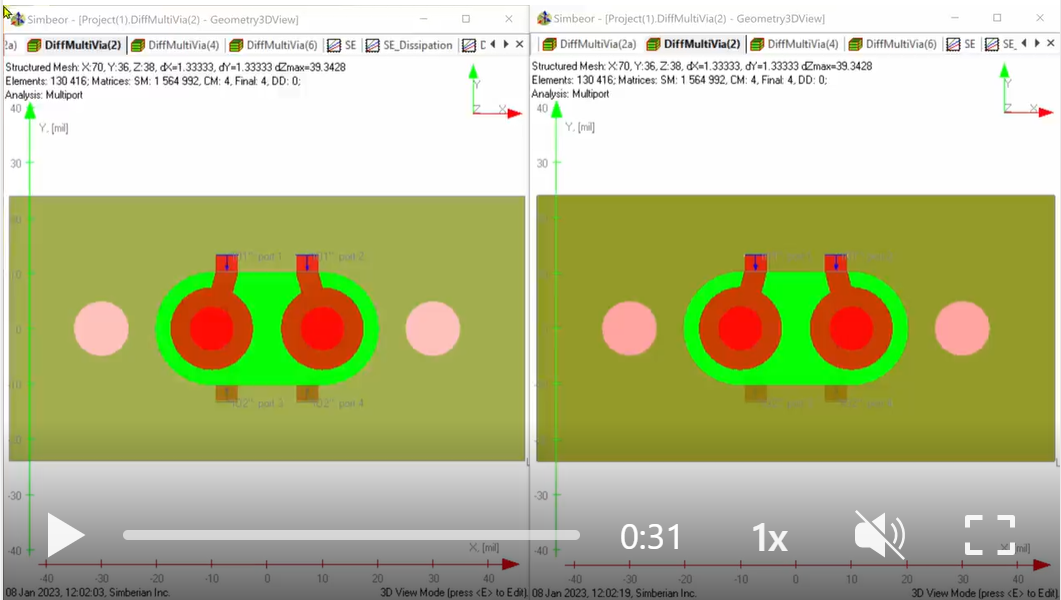
- #041 Differential vias need stitching vias, but how many and what would be the best location?
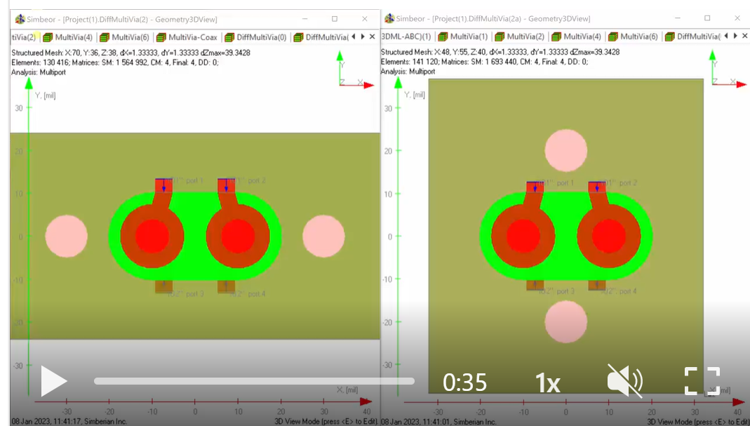
- #040 Can differential vias loose signal energy to radiation? Unfortunately, yes, under certain conditions - at high frequencies and without proper stitching vias.
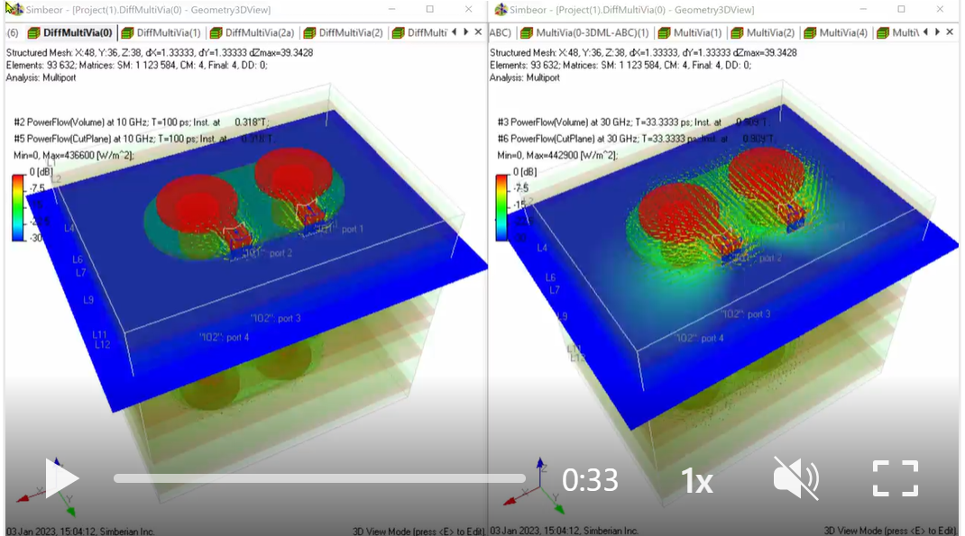
- #039 Consider single-ended vias for 112 Gbps PAM4 signals? Why not? Obviously, with some conditions...
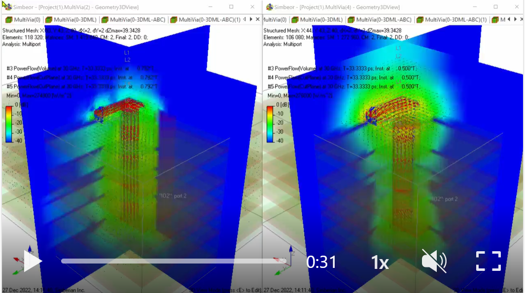
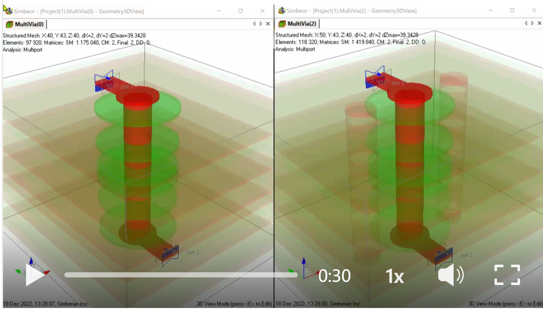
- #038 Here is an illustration of how badly single-ended via needs stitching vias at 10 GHz. This is a continuation of my previous post. The power flow looked similar at 1 GHz with and without stitching. But...
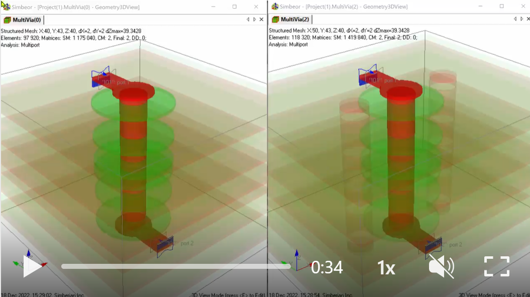
- #037 Does a single-ended via-hole need a stitching via? If yes, then how many? Dissipated power can be used to characterize the via localization quality. This short demo shows...
- #036 What can possibly go wrong with the interconnect impedance? You routed your PCB with trace width and spacing carefully adjusted to have a target impedance from pin to pin (50/100 Ohm for instance).
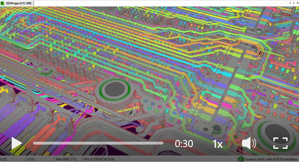
- #035 Magic of fast and accurate PCB interconnect impedance analysis in Simbeor 2022 allows all kinds of experiments with your stackup and material selection on the fly, directly with your actual layout.
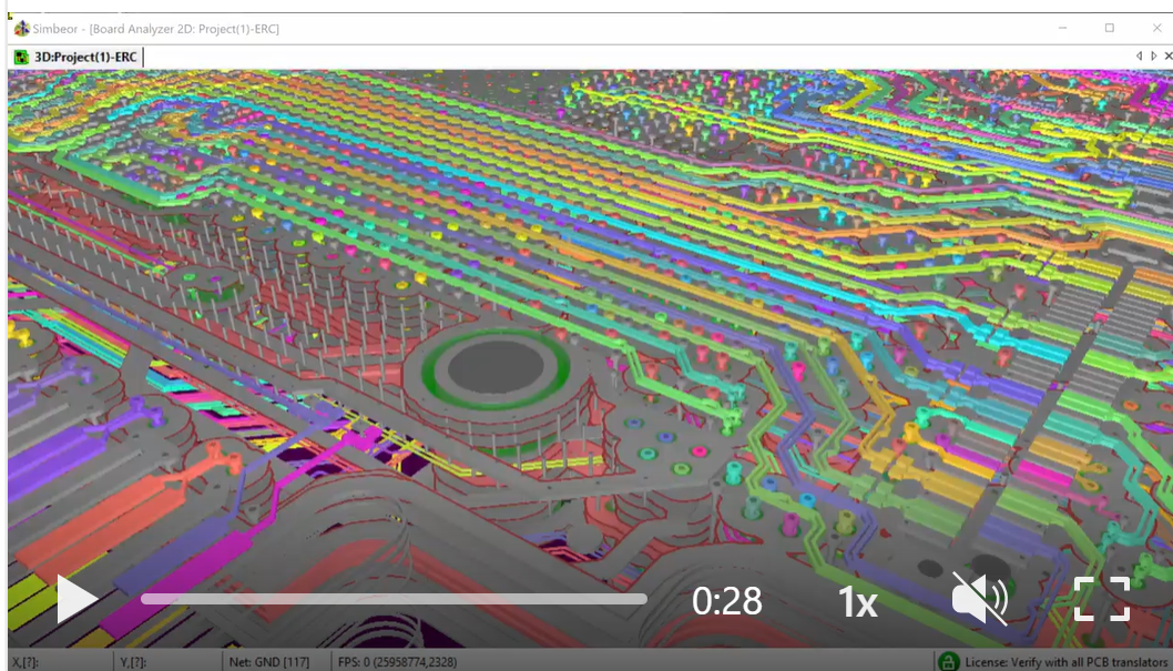
- #034 Imagine you can instantly analyze and see the impedance of every element of PCB interconnect with a click of your mouse - impedance of traces, vias and pads... Is it even possible?... Yes, you can do it now with the next-generation of simulation-based ERC analysis.

- #033 Wondering what is the impedance of a viahole on your PCB and how it is changed by backdrilling? - To "see it", import your whole board design into Simbeor 2022.02 and run the simulation-based ERC analysis with just one click.
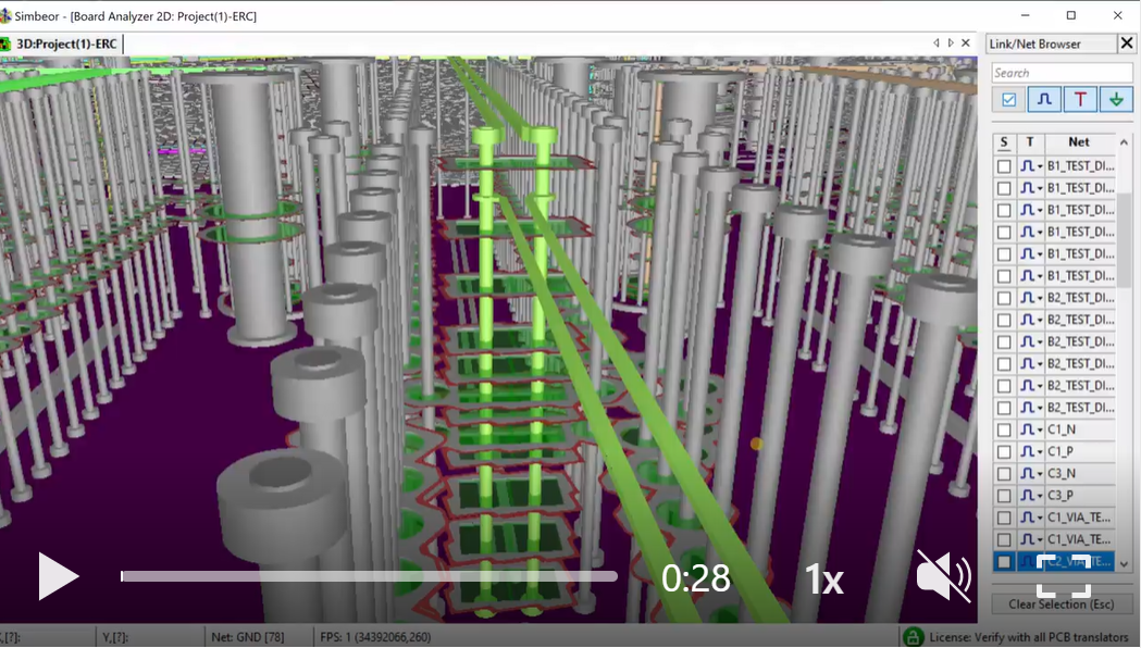
- #032 Wild River Technology's (WRT) Channel Modeling Platform (CMP) used in this webinar is essential for leaning how to design predictable PCB interconnects. With WRT we had the first analysis to measurement validation webinar back in 2014!!!
- #031 Have you seen impedance of interconnects on a flexible PCB? Here it is - the impedance of differential traces over meshed or hatched planes. Once you see it you CAN'T unsee it! But now you can do such analysis in Simbeor 2022.02 with just one click in ERC analysis mode and do S-parameters, TDR, and eye-diagram simulations with just 2 clicks, literally.

- #030 Need an accurate and comprehensive PCB interconnect impedance analysis for the whole board with possible manufacturing adjustments? It can be easily done with Simbeor 2022 in seconds.
- #029 Ever wondered what is the impedance of your PCB interconnects? - traces, pads, vias? It can be quickly modeled with Simbeor Verify License that is $250 per year or $750 perpetual.
- #028 Learn how PCB interconnects work from this conversation with Robert Feranec and demo of Simbeor software...

- #027 If you missed this conversation with Zachariah Peterson at Altium Live, below is the link - it is mostly about the analysis of reference integrity, impedance continuity, crosstalk and other link compliance metrics in new SI Compliance Analyzer tool

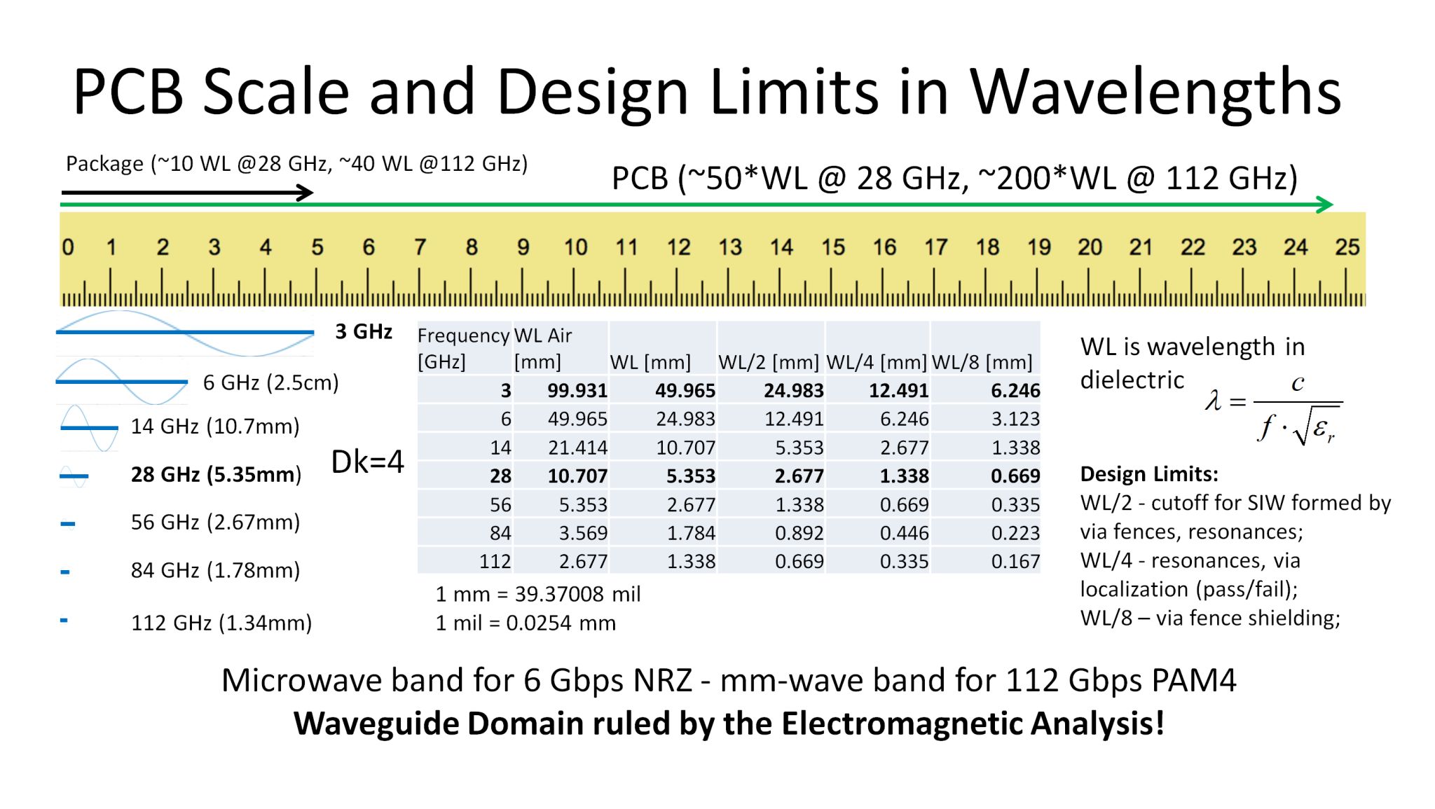
- #026 PCB scale and useful design limits in wavelengths - see more on the bandwidth of your signal, on absorption losses, on impedance and return losses.
- #025 Why Return Loss (RL) is positive? - Larger is better?...
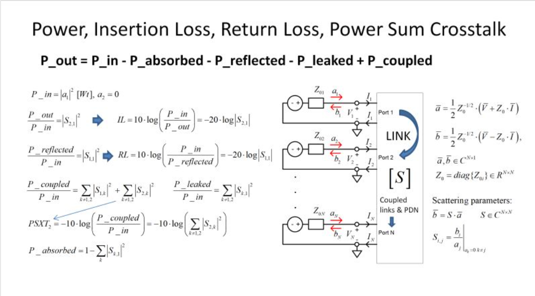
- #024 What happens to a signal on the way to the receiver...
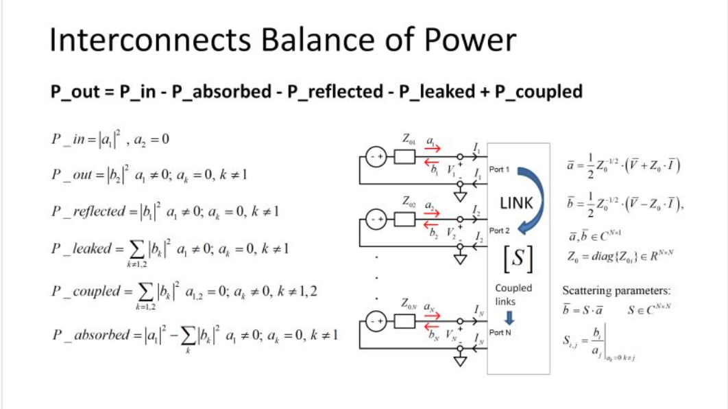
- #023 More "reflections" on signal degradation and discontinuities in interconnects...
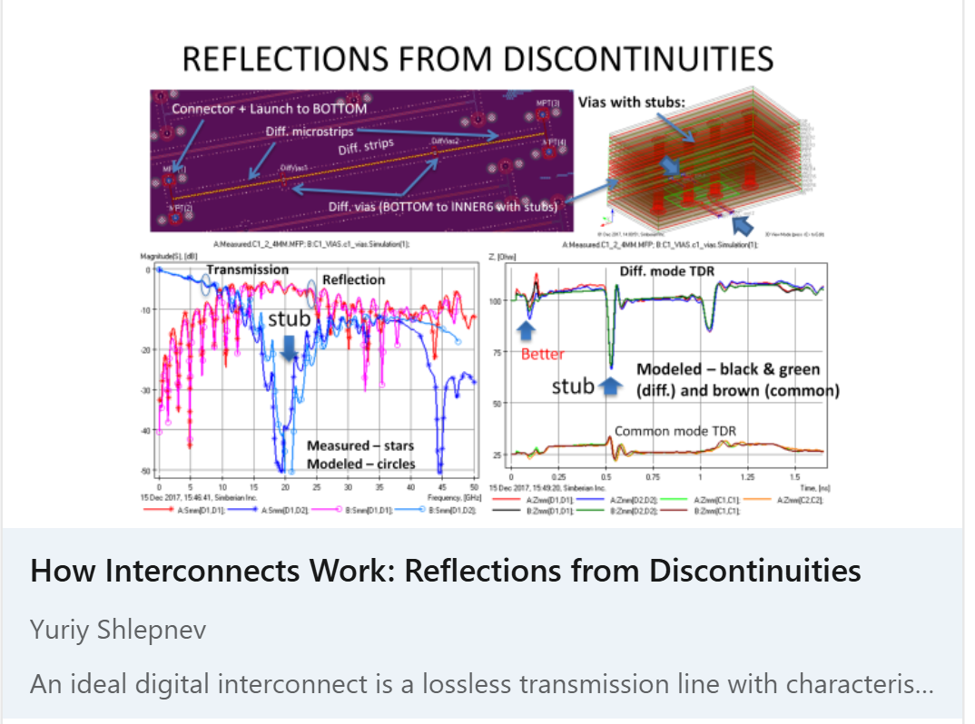
- #022 Analysis of “digital interconnects” is the analog problem in frequency domain where interconnects are simulated as transmission lines defined by characteristic impedance and propagation constant...
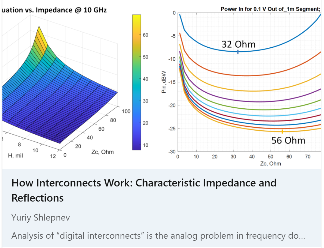
- #021 Here are some "reflections" on the characteristic impedance - definition, analysis and why it is 50 Ohm...
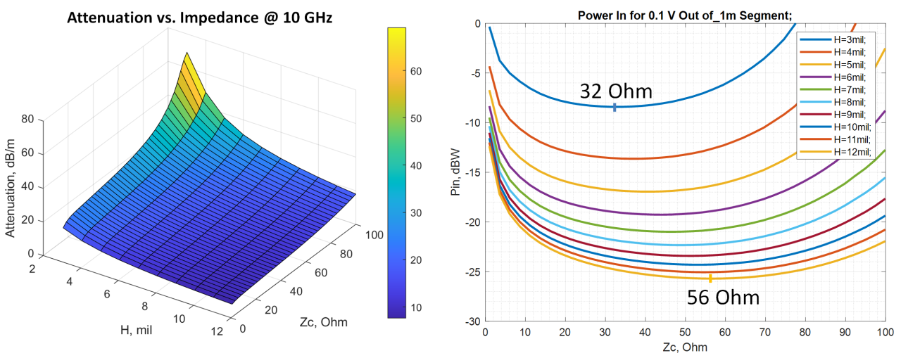
- #020 This is about interconnects contribution to the global warming...
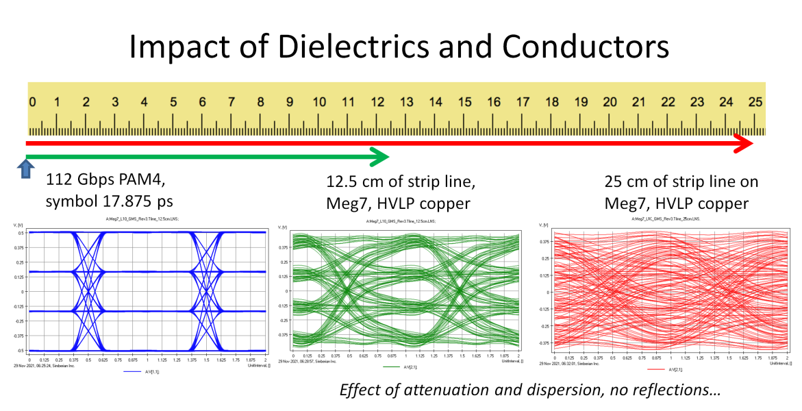
- #019 This article addresses the issue of frequency bandwidth required for the analysis or measurements for PCB or packaging interconnects operating at 6-112 Gbps - it goes from time and spatial domains to the frequency domain...
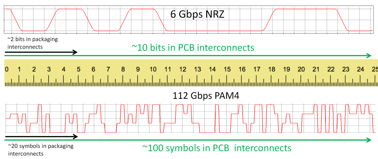
- #018 Do you enjoy the virtual conferences like http://www.epeps.org/? - no travel, very low registration fee, interesting presentations...

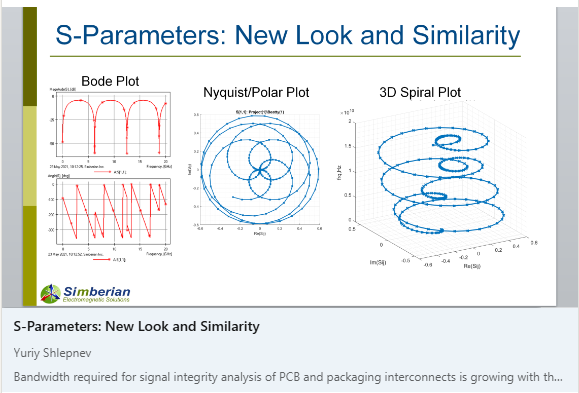
- #017 Wondering how close your interconnect model to measured S-parameters? - here is a formal and very simple way to evaluate the "closeness"...
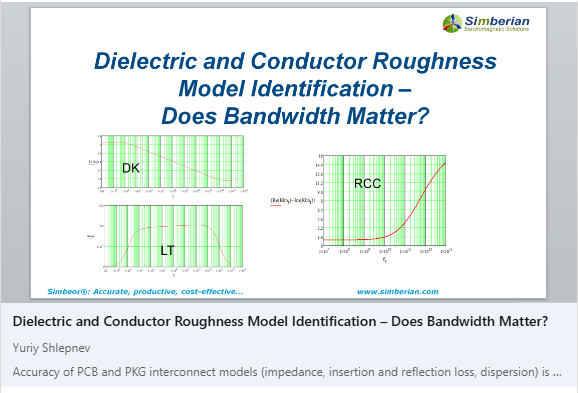
- #016 Frequency-continuous dielectric and conductor roughness models are accurate well above of the measurement and fitting bandwidth - see more in this article...
- #015 Here is more on bends - now with the analysis to measurement correlation thanks to Jose Moreira

- #014 Here are 6 ways to bend PCB traces...

- #013 A trace between parallel planes is a 3-conductor structure - here are the consequences...

- #012 Example of analysis of flexible interconnects with meshed planes...

- #011 Life beyond 10 Gbps: Localize or Fail!

- #010 Moving from 28 Gbps NRZ to 56 Gbps PAM-4 - is it "free lunch"?

- #009 Here is the formula for predictable PCB interconnects design.

- #008 How to design predictable PCB interconnects for 25-30 Gbps data links?

- #007 How Interconnects Work: Microstrip over split planes with remote and close solid reference.

- #006 Learn how to evaluate the effect of cut-outs in reference plane...

- #005 This is the second part of my post on the interconnects over cross-hatched planes - differential microstrip case.

- #004 Learn how to design interconnects over cross-hatched reference planes.

- #003 This is about systematic approach to the analysis to measurement validation for PCB interconnects.

- #002 How Interconnects Work: Conductor roughness modelling and visualization.

- #001 This is an attempt to illustrate the interconnect discontinuity localization principle with the power flow view in a coaxial connector PCB launch.


